
Vision and optical measurement. Start with the part, and the right machine follows.
A thread form, a tray of stampings and a turned shaft can all be measured without touching them, but not on the same machine. The shape of the part, how many you check, which features matter and how fast you need the answer decide between an optical comparator, a vision system and a Sylvac SCAN. This page sorts that out in a few minutes.
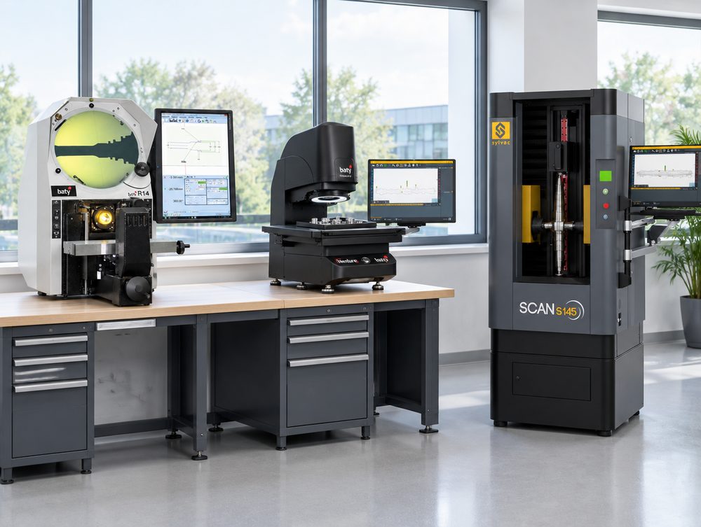
Three ways to measure without touching the part.
All three measure from light and shadow, so soft, thin or delicate parts don't deflect under a gage. They differ in who reads the edge, what shape of part they hold and how many features they check at once.
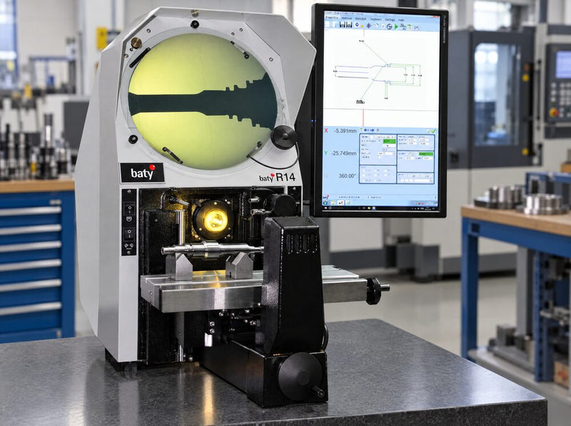
See the profile
The part's shadow is magnified up to 100x on a screen, so an operator can see how far a radius, angle or thread flank sits from the chart or the CAD overlay. Horizontal models take turned parts, vertical models take flat ones.
Explore optical comparators →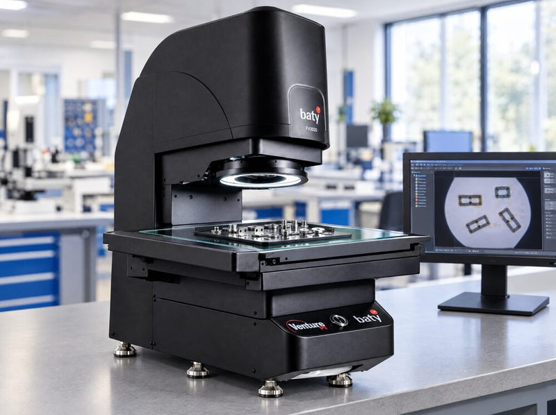
Measure every feature from one image
A camera and software find every edge and check each dimension against tolerance, then write the report. Flash systems measure a whole tray of small parts at once. The Venture XT CNC moves a zoom lens and probe to each feature.
Explore vision systems →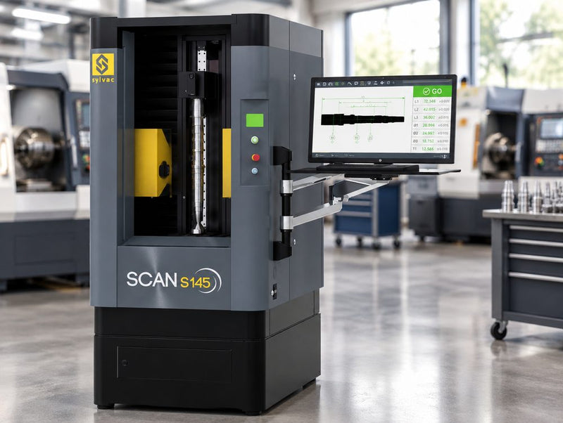
Measure the whole shaft in one pass
The part turns between centers while a camera reads its shadow along the full length: diameters, lengths, runout, and full thread parameters on the tilting T models. GO or NG shows at the machine.
Explore Sylvac SCAN →Which one fits the job?
Read across the rows that matter most to you: the shape of the part, how many you run, the features on the print and how fast you need the answer.
| Optical comparator | Vision system | Sylvac SCAN | |
|---|---|---|---|
| Built for | Profiles on flat and turned parts, read against a chart or CAD overlay | Many features on small parts, measured from a camera image | Round parts: shafts, pins, screws and other turned parts |
| How the part sits | On a glass stage (vertical models) or between centers and in V-blocks (horizontal models) | Placed anywhere on the stage, one part or a tray; side views on the Venture FH | Vertical, between centers or in a chuck, turned by the headstock |
| Part size | Small form tools to large flat parts, by model and screen size | One field of Ø3.9″ × 3.1″ (Ø100 × 80 mm) on most flash models, up to 19.7″ × 15.7″ (500 × 400 mm) on the FV-5040 | Ø1.02″ to Ø7.28″ (Ø26 to Ø185 mm), up to 70.9″ (1800 mm) long |
| Production run | Toolroom, first article, receiving and low to medium volume | Batches and repeat runs of small parts | Every part off the lathe, or a regular sample per shift at the machine |
| Features | Radii, angles, thread form, lengths and profile against a chart | Hole positions, slots, outlines and dozens of dimensions at once; heights and 3D points with the XT CNC probe | Diameters, lengths, shoulders, runout, roundness, and pitch diameter and flank angles on T models |
| Time per part | As long as it takes the operator to read each feature | Seconds for every part in the field | A full 2D scan in under 3 seconds on the S25 and S145 |
| Who finds the edge | The operator, or the optical edge sensor on edge-sensing readouts | The software | The software |
| Results | On the readout; the FUSION readout adds CAD overlay and export | A report with pass/fail on each dimension, Cp and Cpk | GO/NG at the machine, reports and SPC export |
Figures are from published Baty and Sylvac specifications. Each family's page has the full model range and specs.
If your part looks like one of these, start here.
Eight jobs we hear about often, and the family each one usually lands on. Your print may change the answer, which is what a part demo is for.
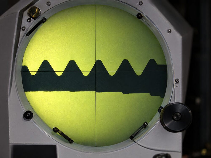
A thread that passes the gage and won't seat
Put the thread on the screen at magnification and you can see which flank is off and by how much.
See comparators →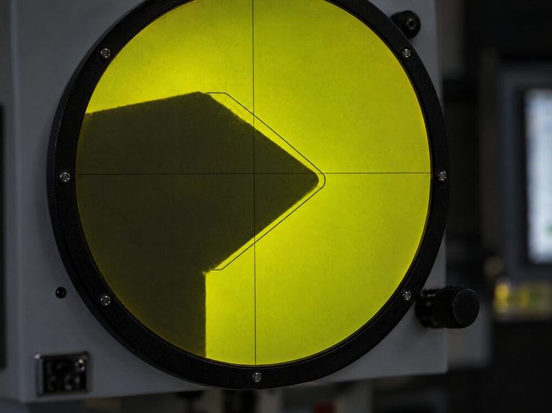
Form tools and inserts after a regrind
Lay the tool's profile over the chart and check the radius and angles before it goes back in the machine.
See comparators →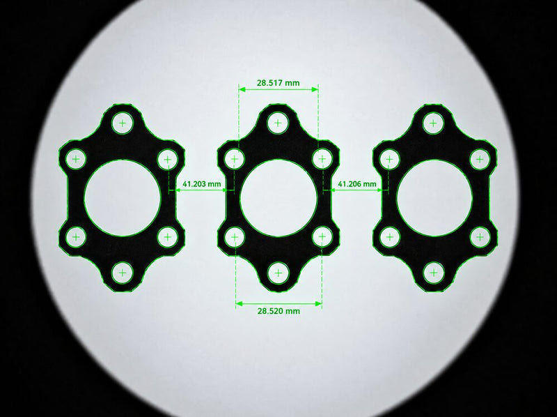
A tray of stampings at first article
Lay the tray on the stage, press measure, and every hole position and slot on every part comes back with pass/fail.
See vision systems →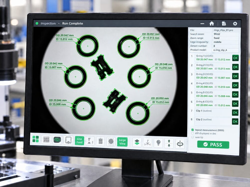
Seals, O-rings and molded parts
Soft parts measured with no contact force, so the reading is the part and not how hard someone squeezed it.
See vision systems →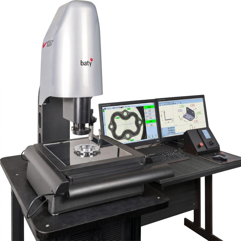
Features on several levels
The Venture XT CNC moves its zoom lens and touch probe to each feature and plays the program back on every part.
See vision systems →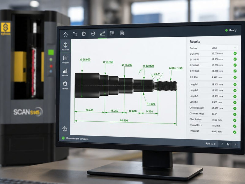
A shaft with twenty dimensions on the print
One scan reads every diameter, length, chamfer and shoulder, and shows GO or NG next to the lathe.
See Sylvac SCAN →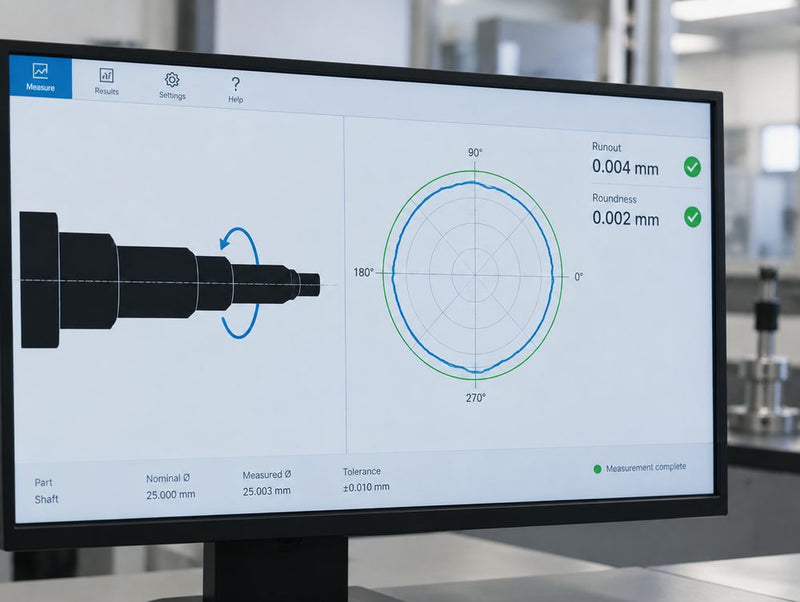
Runout on a ground shaft
The headstock turns the part under the camera for runout, roundness and concentricity without a V-block setup.
See Sylvac SCAN →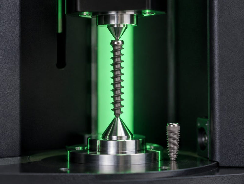
Bone screws and thread parameters in volume
Tilting optics on the T models follow the helix for pitch diameter and flank angles on every screw.
See Sylvac SCAN →Not sure which one? Send us the part and we'll show you which one fits.
The fastest way to settle comparator, vision or SCAN is to see your own part measured. If you can't send one yet, describe the job and an application engineer will take it from there.
Tell us about the parts
The print, the features you can't measure well today, the tolerance, and how many parts you check per shift.
Send samples, or watch live
Ship sample parts to Fowler in Canton, Massachusetts, or set up a live video session with your parts on the machine.
Get the results and a recommendation
You get measurement results from your own parts and the family and model we'd quote for them.
Requests go to the Fowler application engineer who covers your state. Prefer the phone? Call (800) 788-2353.
Tell us about the parts, the features that give you trouble and how you want to see them measured. An application engineer replies with next steps.
Vision and optical measurement FAQs
Both measure the part's outline from light and shadow. On a comparator the magnified shadow goes on a screen and the operator reads each feature, which suits profile work like threads, radii and form tools. On a vision system a camera and software find every edge, check each dimension against tolerance and write the report, which suits repeat runs with many features.
When the part is round and you check many features on a lot of them. A SCAN holds the part between centers, reads the full length in one pass and turns it for runout, so a shaft with twenty dimensions gets checked in one cycle; Sylvac puts a full SCAN inspection at 30 to 60 seconds. A horizontal comparator suits fewer parts where an operator wants to see the profile on a screen.
For batches of small parts, a flash vision system, because every part in the field is measured from one image. For round parts, a SCAN, with a full 2D scan in under 3 seconds on the S25 and S145. A comparator goes at the speed of the operator, which is often all a toolroom or a first-article check needs.
Sometimes, when the parts are similar. The Venture FH, for example, looks at parts from the side, which suits fasteners, pins and connectors. If your parts split between flat and round, send a sample of each and we'll tell you whether one machine covers them or two will pay off.
Yes. Send sample parts and the print, and we'll measure them on whichever of the three fits and send back the results with a recommended model.
Optical comparators
Horizontal and vertical Baty comparators, five readouts, fixtures and retrofits.
Explore comparators →Every feature, one imageVision systems
Baty Velo, Venture FV and FH flash systems, and the Venture XT CNC.
Explore vision systems →Round parts, one passSylvac SCAN
Five sizes from Ø1.02″ to Ø7.28″, with tilting optics and a touch probe option.
Explore Sylvac SCAN →