
The camera picks the edge, so the operator doesn't
Sub-pixel edge detection finds each edge in the image and fits the feature to it. Two operators loading the same part get the same result, because neither of them decides where the edge is.

A tray of stampings waits at first-article while someone measures each one with calipers and types the numbers into a spreadsheet. A vision system measures from a camera image, finds every edge itself and checks it against the tolerance, so the result is the same whoever loaded the part. Up to a thousand parts measured in one pass, in seconds.
Answer three questions about the parts and what you need to measure. You'll get a starting model.
Start the fit guide →02 / AskDescribe the part, the features and the tolerance. Our application engineers love to solve tricky inspection challenges. Shoot us an email with and a copy of the drawing and our team will find the best solution for the best value.
Ask an engineer →03 / Prove itSend us a sample part and the print/drawing. We measure them on the system we think is the best fit... and you can join in on a video call to watch how it's done (and see the results).
Request a part demo →Calipers and comparators depend on someone lining up on an edge, and two people line up a little differently. Every reading then has to be written down or typed in before anyone can act on it. While a lot sits at inspection waiting for that, the machine keeps cutting parts nobody has checked.
Sub-pixel edge detection finds each edge in the image and fits the feature to it. Two operators loading the same part get the same result, because neither of them decides where the edge is.
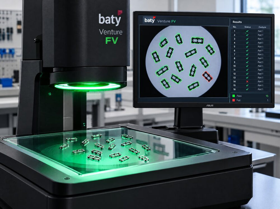
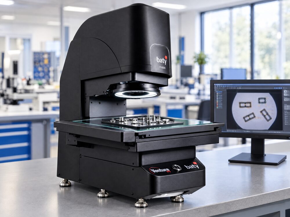
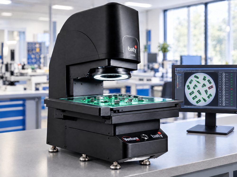
On the Velo and Venture FV, every programmed edge inside the field of view is measured from a single image, whether there's one part on the stage or a full tray.
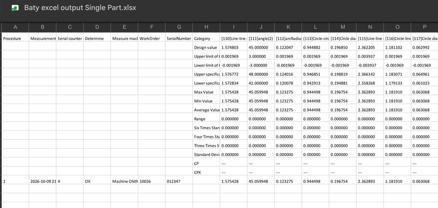
Results go to an Excel-compatible report with pass/fail on each dimension, a dimensioned image of the part and process capability (Cp and Cpk). Nobody retypes a number.
Both measure from a camera image with automatic edge detection. They differ in how the camera gets to the feature.

A large telecentric lens sees the whole field at once, Ø3.9″ × 3.1″ (Ø100 × 80 mm) on most models. Put one part or a tray of parts anywhere in the field, press measure, and every programmed dimension comes back with pass/fail. Built for small parts in volume: stampings, fasteners, molded parts, seals and turned parts.
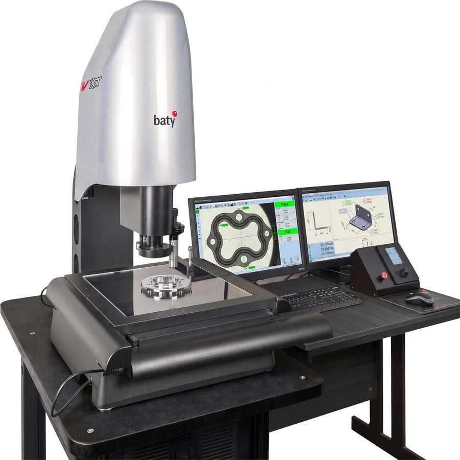
A 6.5:1 zoom lens on a 3-axis CNC stage moves to each feature, changing magnification and focus as programmed, and a touch probe adds points the camera can't see. You measure the first part once and the system writes the program from it. Built for parts with features on several levels, small features that need high magnification, and 3D points.
A vision system is perfect for when the same features get checked on a lot batch of parts, or when the part is too small or too soft to put a gage on it
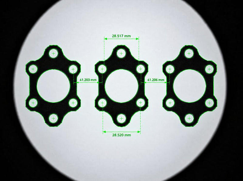
Hole positions, slots and profiles on stampings, gaskets and brackets.
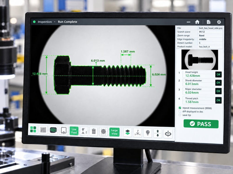
Head details, shank diameters and thread form, viewed from the side on the FH.
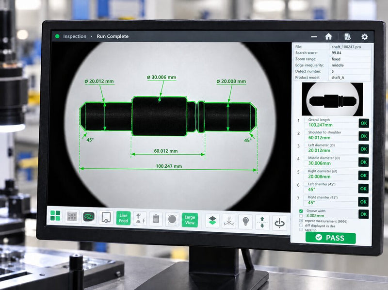
Diameters, lengths, shoulders and chamfers on shafts and pins.
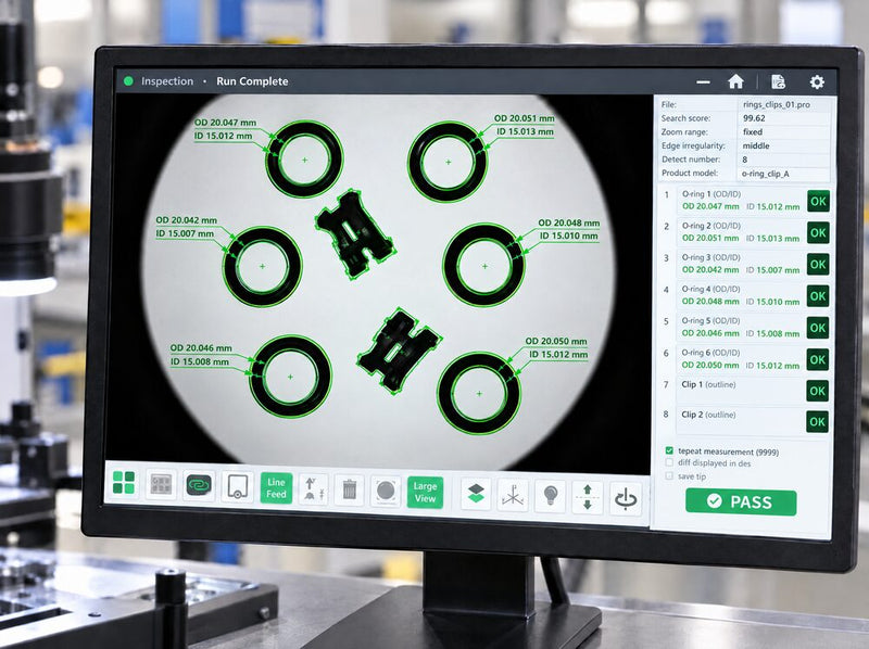
Seals, O-rings and moldings measured with no contact force.
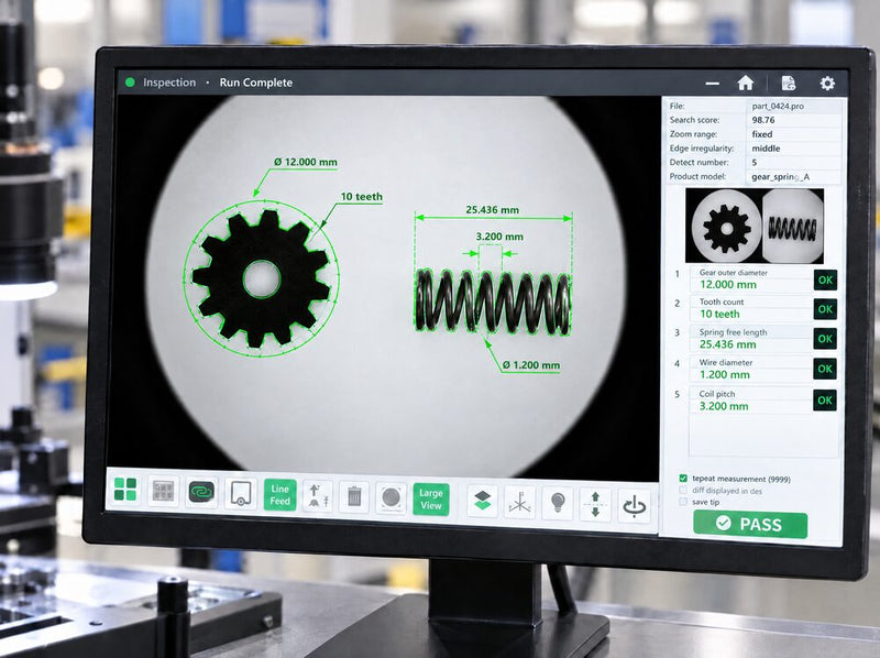
Dedicated software functions for gears, threads, O-rings and springs.
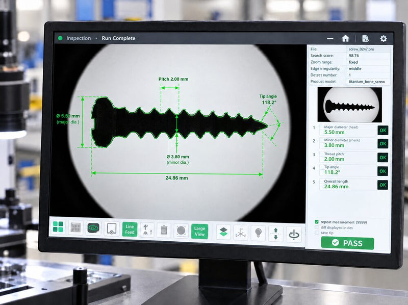
Bone screws, implants and micro tools in the high-magnification field.
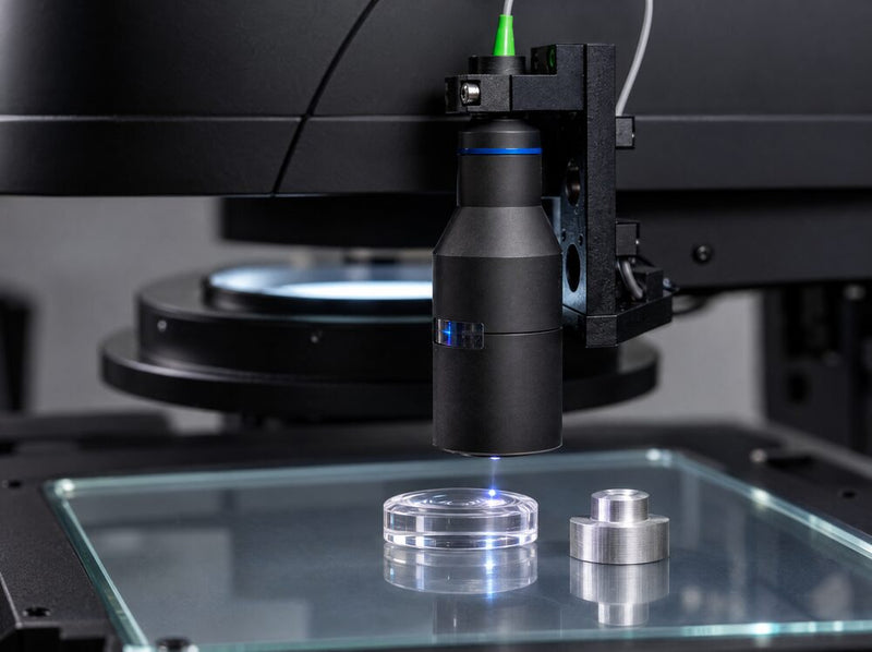
With the confocal probe or the XT CNC touch probe, transparent parts included.

Roundness, concentricity and runout with the rotary axis or the FH-1080AF.
1. Helps pick the kind of system 2. The the size. 3. Needs beyond the outline.
Pick an answer above first.
Velo, Venture FV and Venture FH measure everything in the field at once. The Venture XT CNC moves the camera and probe to each feature.

Built for repeat inspection of simple parts, in a compact bench unit that moves between cells. Fixed Ø3.9″ × 3.1″ (Ø100 × 80 mm) field, ±0.00012″ (±3 µm).
Ask about the Velo →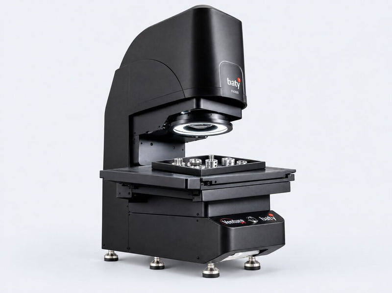
Built for batches of small parts and parts bigger than one field, on fixed or CNC stages up to 11.8″ × 8.3″ (300 × 210 mm). Seven models, single or dual field.
Compare the FV models →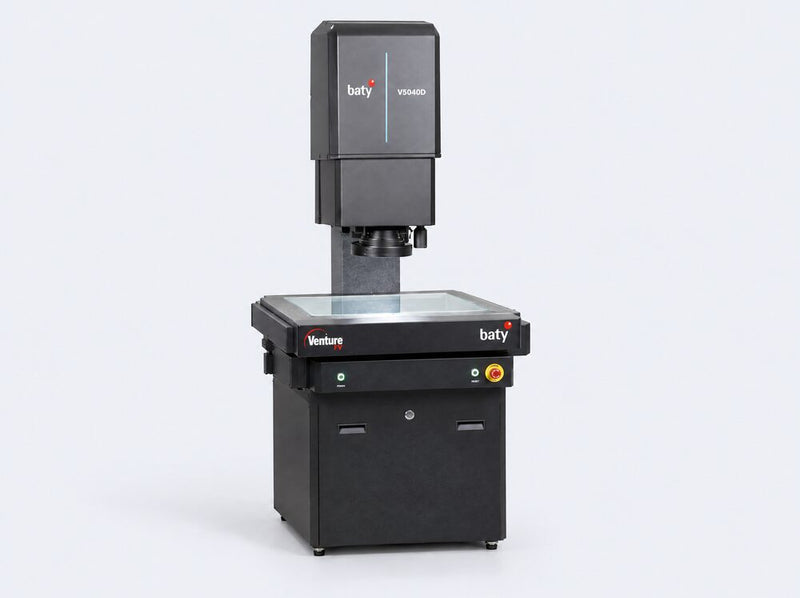
Built for large parts and large batches, on a floor-standing granite base with a 19.7″ × 15.7″ × 9.8″ (500 × 400 × 250 mm) range. Single or dual field.
Ask about the FV-5040 →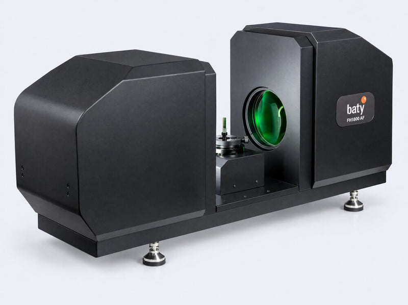
Built for fasteners, pins, connectors and tools viewed from the side, on a fixed or CNC rotating stage. Ø3.9″ × 3.1″ (Ø100 × 80 mm) field.
Ask about the Venture FH →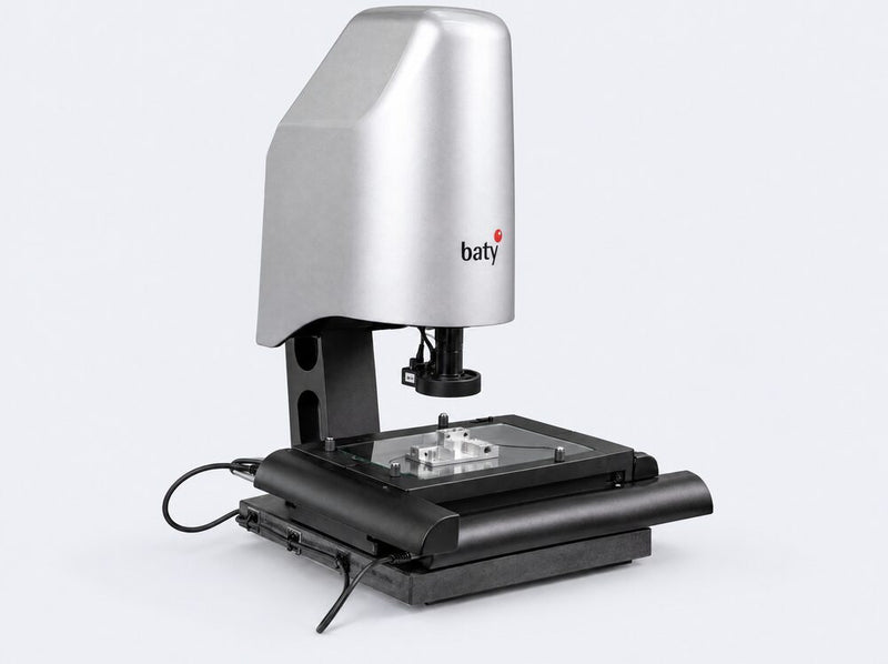
Built for smaller parts with 3D features, with 6.5:1 CNC zoom and a TP20 touch probe option. 9.8″ × 4.6″ × 5.9″ (250 × 118 × 150 mm) travel.
Explore XT 2510 configurations →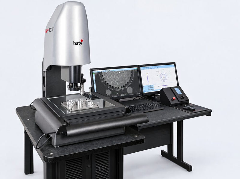
Built for larger parts and fixtures holding several parts, with TP20 or SP25 probe options. 11.8″ × 11.8″ × 7.9″ (300 × 300 × 200 mm) travel.
Explore XT 3030 configurations →| Model | Velo FV-1080V | Venture FV benchtop | Venture FV-5040 | Venture FH | Venture XT 2510 CNC | Venture XT 3030 CNC |
|---|---|---|---|---|---|---|
| Type | Flash, fixed field | Flash, single or dual field | Flash, single or dual field | Flash, horizontal light path | CNC zoom optics with touch probe | CNC zoom optics with touch probe |
| Platform | Compact benchtop | Benchtop, fixed or CNC stage | Floor-standing, granite base | Benchtop, fixed or CNC rotating stage | 3-axis CNC, joystick and touchscreen | 3-axis CNC, joystick and touchscreen |
| Measuring range | Ø3.9″ × 3.1″ (Ø100 × 80 mm), one field | Up to 11.8″ × 8.3″ (300 × 210 mm) | 19.7″ × 15.7″ × 9.8″ (500 × 400 × 250 mm) | Ø3.9″ × 3.1″ (Ø100 × 80 mm), one field | 9.8″ × 4.6″ × 5.9″ (250 × 118 × 150 mm) | 11.8″ × 11.8″ × 7.9″ (300 × 300 × 200 mm) |
| Field of view | Ø3.9″ × 3.1″ (Ø100 × 80 mm) | Ø3.9″ × 3.1″ (Ø100 × 80 mm) or Ø5.9″ × 4.3″ (Ø150 × 110 mm); see the model table | 3.6″ × 2.4″ (92 × 62 mm); dual field adds 0.79″ × 0.59″ (20 × 15 mm) | Ø3.9″ × 3.1″ (Ø100 × 80 mm) | 6.5:1 CNC zoom | 6.5:1 CNC zoom |
| Accuracy in the field | ±0.00012″ (±3 µm) | ±0.00011″ (±2.8 µm) large field, ±0.00004″ (±1 µm) small field, on Ø100 mm models | ±0.00011″ (±2.8 µm) large field, ±0.00004″ (±1 µm) small field | ±0.00011″ (±2.8 µm) | Ask us | Ask us |
| Repeatability | ±0.00004″ (±1 µm) | Ask us | Ask us | ±0.00004″ (±1 µm) | Ask us | Ask us |
| Scale resolution | Ask us | Ask us | Ask us | Ask us | 0.00002″ (0.5 µm) | 0.00002″ (0.5 µm) |
| Camera | 20 megapixel | 12 or 20 megapixel by model | 12 or 20 megapixel | 20 megapixel | High-resolution color camera | High-resolution color camera |
| Profile light | Telecentric green LED | Telecentric LED | Telecentric white LED | Telecentric LED | Collimated under-stage light | Collimated under-stage light |
| Surface light | White LED ring | 4-zone white LED ring, motorized green ring, optional coaxial | 4-zone white LED ring, motorized green ring, optional coaxial | High-angle LED ring on the FH-1080AF | Programmable 64-LED ring, coaxial | Programmable 64-LED ring, coaxial |
| Focus | Autofocus | Motorized autofocus | Motorized autofocus | Autofocus on the FH-1080AF, 2.2″ (55 mm) travel | CNC autofocus | CNC autofocus |
| Probe and rotary options | Ask us | Confocal probe (FV-3020), rotary axis | Confocal probe, rotary axis | CNC rotating stage (FH-1080AF) | TP20 touch probe | TP20 or SP25 touch probe, probe changer rack |
| Software | Ask us | Fusion FV | Fusion FV | Fusion FV | Fusion 3D (MK4) | Fusion 3D (MK4) |
| Size and weight | 17.9″ × 8.5″ × 26.0″, 60 lb (455 × 215 × 660 mm, 27 kg) | Ask us | Ask us | 31.1″ × 9.1″ × 15.2″, 60 lb (790 × 230 × 385 mm, 27 kg) | Ask us | Ask us |
| Max part load | 6.6 lb (3 kg) | Ask us | Ask us | 6.6 lb (3 kg) | Ask us | Ask us |
Published Baty specifications. Flash system accuracy is within the field of view; accuracy across the full stage for each Venture FV model is in the next table.
Fixed-stage models measure within one field. CNC stage models stitch images across the stage. Dual-field models add a second, higher-magnification view.
| Model | FV-1080 | FV-1080D | FV-1511 | FV-2020 | FV-2113P | FV-3020 | FV-3021 | FV-5040 | FV-5040D |
|---|---|---|---|---|---|---|---|---|---|
| Stage | Fixed | Fixed | Fixed | CNC | High-precision CNC | CNC | CNC | CNC, floor-standing | CNC, floor-standing |
| Fields | Single | Dual | Dual, large lens | Dual | Dual | Dual | Dual, large lens | Single | Dual |
| Measuring range, large field | One field | One field | One field | 7.9″ × 7.9″ (200 × 200 mm) | 8.3″ × 5.1″ (210 × 130 mm) | 11.8″ × 7.9″ (300 × 200 mm) | 11.8″ × 8.3″ (300 × 210 mm), R75 corners | 19.7″ × 15.7″ (500 × 400 mm) | 19.7″ × 15.7″ (500 × 400 mm) |
| Measuring range, small field | n/a | One field | One field | 5.1″ × 5.1″ (130 × 130 mm) | 7.9″ × 3.9″ (200 × 100 mm) | 9.1″ × 5.1″ (230 × 130 mm) | 7.9″ × 5.3″ (200 × 135 mm) | n/a | 16.9″ × 13.8″ (430 × 350 mm) |
| Large field of view | Ø3.9″ × 3.1″ (Ø100 × 80 mm) | Ø3.9″ × 3.1″ (Ø100 × 80 mm) | Ø5.9″ × 4.3″ (Ø150 × 110 mm) | Ø3.9″ × 3.1″ (Ø100 × 80 mm) | 0.98″ × 0.67″ (25 × 17 mm) | Ø3.9″ × 3.1″ (Ø100 × 80 mm) | Ø5.9″ × 4.3″ (Ø150 × 110 mm) | 3.6″ × 2.4″ (92 × 62 mm) | 3.6″ × 2.4″ (92 × 62 mm) |
| Small field of view | n/a | 0.79″ × 0.63″ (20 × 16 mm) | 1.97″ × 1.38″ (50 × 35 mm) | 0.79″ × 0.63″ (20 × 16 mm) | 0.31″ × 0.20″ (8 × 5 mm) | 0.98″ × 0.79″ (25 × 20 mm) | 1.97″ × 1.38″ (50 × 35 mm) | n/a | 0.79″ × 0.59″ (20 × 15 mm) |
| Accuracy in the field, large | ±0.00011″ (±2.8 µm) | ±0.00011″ (±2.8 µm) | ±0.0002″ (±5 µm) | ±0.00011″ (±2.8 µm) | ±0.00008″ (±2 µm) | ±0.00011″ (±2.8 µm) | ±0.0002″ (±5 µm) | ±0.00011″ (±2.8 µm) | ±0.00011″ (±2.8 µm) |
| Accuracy in the field, small | n/a | ±0.00004″ (±1 µm) | ±0.00008″ (±2 µm) | ±0.00004″ (±1 µm) | ±0.00003″ (±0.7 µm) | ±0.00004″ (±1 µm) | ±0.00008″ (±2 µm) | n/a | ±0.00004″ (±1 µm) |
| Accuracy across the stage, large field | n/a | n/a | n/a | ±(5 + L/50) µm | ±(4 + L/50) µm | ±(5 + L/50) µm | ±(7 + L/50) µm | ±(5 + L/200) µm | ±(5 + L/200) µm |
| Accuracy across the stage, small field | n/a | n/a | n/a | ±(3 + L/50) µm | ±(2.7 + L/50) µm | ±(3 + L/50) µm | ±(4 + L/50) µm | n/a | ±(3 + L/200) µm |
Published Baty specifications. L is the measured length in mm. The confocal probe is offered on the FV-3020 and FV-5040.
A vision measurement is only as good as the image under it: whether the lens distorts the edge, how the light hits it, and whether the software knows which part it's looking at.
This is how a run goes on the Venture FV. On the Venture XT CNC, the run is a stored program the machine plays back.
Place one part or a batch anywhere in the field. The software doesn't need them lined up.
Automatic part recognition matches each part to its stored inspection, and character recognition reads its part number.
Edge detection measures every programmed dimension on every part, each under the lighting it was programmed with. On CNC stage models, parts bigger than the field get stitched images.
Each part shows pass or fail on screen. Part grading sorts parts into size classes for matched assembly.
Single-part reports with a dimensioned image, batch reports listed by part number, and SPC with Cp and Cpk, saved as Excel-compatible files where you tell it.
Most vision system questions get answered fastest with parts in hand. If you can't send any yet, send us a drawing and we'll 3D print a prototype part and our application engineers will take it from there.
The print, the CAD file, the features you can't measure well today, the tolerance, and how many parts you check per shift.
Ship sample parts to Fowler in Canton, Massachusetts, and schedule a live video session with the parts on the stage.
You get the measurement results from your own parts and the model, optics and options we'd quote for them.
Requests go to the Fowler application engineer who covers your state. Prefer the phone? Call (800) 788-2353.
Tell us about the parts, the features that are tricky and how you want to see them measured. An application engineer will get back to you with a plan and and schedule a time for a live video demo
Flash systems (Velo, Venture FV and Venture FH) measure everything inside a large field of view from one image, which suits batches of small parts and repeat inspection. The Venture XT CNC moves a zoom lens and touch probe to each feature, which suits parts with features on several levels, small features that need high magnification, and 3D points. If your parts could go either way, send one and we'll show you both.
A single-field Venture FV has one large view of the stage. A dual-field model adds a second, higher-magnification view for small features, with tighter accuracy in that view: ±0.00004″ (±1 µm) against ±0.00011″ (±2.8 µm) in the large field on the Ø100 mm models.
A telecentric lens collects only light that runs parallel to the lens axis, so the image doesn't grow or shrink when the part sits a little higher or lower, and an edge near the corner of the field measures the same as one in the center. That's what lets a flash system measure a whole tray from one image.
Yes, on the CNC stage models. The Venture FV-2020, FV-2113P, FV-3020, FV-3021 and FV-5040 move the stage and stitch images together across the measuring range. The Velo and the fixed-stage FV models measure within one field. The Venture XT CNC moves to each feature, so the limit is its travel.
A camera measures in the plane of the image. For heights, depths, flatness and thickness, the Venture FV-3020 and FV-5040 take the optional confocal probe, which also measures transparent parts, and the Venture XT CNC takes a TP20 or SP25 touch probe.
A comparator puts the magnified shadow on a screen in front of the operator, which suits profile work like threads, radii and form tools where seeing the whole outline helps. A vision system measures from a camera image under a stored program and writes the report, which suits repeat runs of many features. If you're weighing both, an application engineer can walk you through them with your part.
Yes. Send sample parts and the print, and we'll measure them on the system you're considering and send back the results with a recommended setup.
Send samples and the print. You get the results from your own parts.
Request a demo →AskDescribe the job and get a recommendation from the engineer who covers your region.
Ask an engineer →LearnEvery model, option and accessory, with full specs.
Open the vision system brochure →