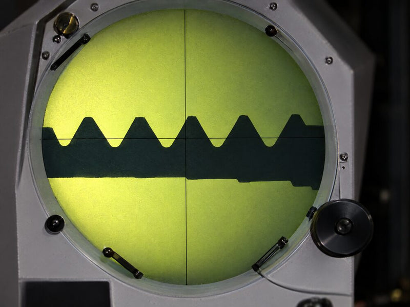
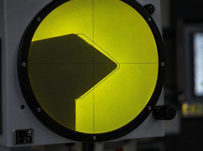
Non-contact, 0.5 µm scales, CAD overlay

Fowler Baty optical comparators. See where the profile is off without touching the part.

A thread passes the go gage and still won't seat at assembly. A thin stamping flexes the moment the caliper jaws close on it. An optical comparator measures the part's shadow at up to 100x, so you see how far each radius, angle or thread flank sits from the print.

Fowler offers:

Horizontal and vertical comparators, five readouts, fixtures and retrofits

Fowler Baty horizontal optical comparator with Fusion software in a QC lab
Fowler Baty horizontal optical comparator
Why an optical comparator?

Go/no-go tells you pass or fail. Our optical comparator tells you why.

Calipers, micrometers and plug gages each check one feature per setup. Every tool change is another chance for the part to shift and another reading that depends on who's holding the tool. When a lot gets rejected, an attribute gage leaves you with a count of failures and nothing about which feature drifted or by how much.

Fowler Baty R14 horizontal optical comparator on the shop floor
01 / One setup

Radii, angles, lengths and thread forms from the same fixture

Load the part once and measure every external feature without moving it to another tool. The stage runs on 0.00002″ (0.5 µm) linear scales, so the number comes from the scale and not from how hard someone turned a thimble.

Fusion comparator software laying a CAD drawing over the measured profile
02 / CAD compare

Lay the drawing over the part

With the FT2-E FUSION readout you import the .dxf, scan the edge, and the software best-fits the profile to the CAD and marks each feature in or out of tolerance. The output is a dimensioned drawing your customer can read without a phone call.

Flat part on the lit glass stage of a Fowler Baty optical comparator
03 / Zero force

Measure parts that move when you touch them

The comparator measures a shadow, so nothing presses on the part. Thin stampings, plastic extrusions, rubber seals and small medical implants keep the shape they had on the bench while you measure them.

Fit guide

Which comparator fits your part? Three questions.

The model comes down to how the part sits and how big it is. The readout comes down to what happens to the number after you take it.

1

How does the part sit for inspection?

2

How big is the work, and where does it live?

Pick an answer above first.

3

What happens to the reading after you take it?

The lineup

Horizontal for turned parts. Vertical for flat ones.

On a horizontal machine, light crosses the stage sideways, around a part held in V-blocks, a vise or between centers. On a vertical machine, light comes up through a flat glass stage under parts that lie on it.

Fowler Baty R14 horizontal optical comparator
HORIZONTAL LIGHT PATH

Fowler Baty R14

Built for smaller turned and threaded parts on a workshop bench, with a compact, lightweight chassis. 13.4″ (340 mm) screen, 6.9″ × 3.9″ travel.

Explore R14 configurations →
Fowler Baty horizontal optical comparator with Fusion readout
HORIZONTAL LIGHT PATH

Fowler Baty R400

Built for the shop floor or the standards room, with a bigger screen and a quick-release rapid traverse. 15.8″ (400 mm) screen, 11.8″ × 5.9″ travel.

Explore R400 configurations →
Fowler Baty R600 optical comparator
HORIZONTAL LIGHT PATH

Fowler Baty R600

Built for large or heavy turned work in V-blocks and centers, with a powered Y-axis and a hooded screen for bright shops. 23.6″ (600 mm) screen, 17.7″ × 7.9″ travel.

Explore R600 configurations →
Fowler Baty SM300 vertical optical comparator
VERTICAL LIGHT PATH

Fowler Baty SM300

Built for small flat parts at the station, with the GMR geometric readout and a built-in printer as standard. 11.8″ (300 mm) screen, 5.9″ × 2.0″ travel.

See the SM300 →
Fowler Baty SM350 vertical optical comparator
VERTICAL LIGHT PATH

Fowler Baty SM350

Built for larger flat parts in a production cell or QC room, on a heavy-duty stage with rapid traverse on both axes. 13.8″ (350 mm) screen, 9.8″ × 4.9″ travel.

Explore SM350 configurations →
Fowler Baty SM20 vertical optical comparator
VERTICAL LIGHT PATH

Fowler Baty SM20

Built for heavy-duty flat-part inspection standing up, with an angled screen and twin fiber-optic surface lights. 19.7″ (500 mm) screen, 9.8″ × 4.9″ travel.

Ask about the SM20 →
Specifications

Side by side, for the those who like the numbers.

ModelR14R400R600SM300SM350SM20
Light pathHorizontalHorizontalHorizontalVerticalVerticalVertical
PlatformBenchtopBenchtop, or floor with optional cabinet standFloor-standing, large formatBenchtopHeavy-duty benchtopFloor-standing
Screen13.4″ (340 mm), 90° crosslines, chart clips15.8″ (400 mm), 90° crosslines, chart clips23.6″ (600 mm), 90° crosslines, hood and curtains11.8″ (300 mm) fine ground glass, crosshairs, chart clips13.8″ (350 mm)19.7″ (500 mm) angled, 90° crosslines, chart clips
Stage travel (X × Y)6.9″ × 3.9″ (175 × 100 mm)11.8″ × 5.9″ (300 × 150 mm)17.7″ × 7.9″ (450 × 200 mm)5.9″ × 2.0″ (150 × 50 mm)9.8″ × 4.9″ (250 × 125 mm)9.8″ × 4.9″ (250 × 125 mm)
Stage driveSlotted cast iron stage, one machined slotSlotted cast iron stage, plain rod drive, quick-release rapid traverseHeavy-duty stage, two machined slots, powered 7.9″ (200 mm) Y-axis with joystickLinear scale stageHeavy-duty stage, plain rod drives, rapid traverse on both axesHeavy-duty stage, quick-release X and Y clutches
Scale resolution0.00002″ (0.5 µm)0.00002″ (0.5 µm)0.00002″ (0.5 µm)0.00002″ (0.5 µm)0.00002″ (0.5 µm)0.00002″ (0.5 µm)
Lens magnifications10x, 20x, 25x, 50x, 100x10x, 20x, 50x, 100x10x, 20x, 50x, 100x10x, 20x, 50x, 100xAsk us10x, 20x, 50x, 100x
Lens mountingSingle mountSingle mount4-position rotating turretSingle mountSingle mount or optional 3-lens turretSingle mount or optional 3-lens turret
Max part heightAsk usAsk usAsk us3.1″ (80 mm)Ask usAsk us
Profile illuminationHalogen with green filterLED, optional green filterHalogen with green filterBuilt-inBuilt-inHalogen with green filter
Surface illuminationFiber opticFiber opticFiber opticBuilt-inIncludedTwin fiber optic, full color
Thread and tool setupLight source helix ±7°Light source helix ±7°Workstage helix rotation ±15° for threads and cutting toolsAsk usHelix adjustmentLight source helix adjustment
Angle readoutDigital, to 1 minuteDigital, to 1 minuteDigitalThrough the GMR readoutDigital angle protractorDigital
Edge sensorWith GXL-E or FT2-EWith GXL-E or FT2-EWith GXL-E or FT2-EAsk usWith GXL-E or FT2-EOptional automatic edge sensor
ReadoutXLS, GXL, GXL-E or FT2-EXLS, GXL, GXL-E or FT2-EXLS, GXL, GXL-E or FT2-EGMR with built-in printer, standardXLS, GXL, GXL-E or FT2-EAsk us

All models read to 0.00002″ (0.5 µm). Lenses, fixtures and readouts are configured per order.

How it works

The details that keep the reading accurate.

Most of what makes a comparator reading trustworthy happens before anyone looks at the number: how the light hits the part, how the edge gets picked up, and how the part sits on the stage.

→
Helix adjustment
Tilt the light source to match the thread helix (±7° on the R14 and R400, or rotate the R600 stage up to ±15°) and the screen shows the true flank form instead of a smeared shadow.
→
Automatic edge detection
The sensor registers the light-to-dark edge and logs the point itself. The reading is operator agnostic.
→
Quick-release stage
Clutches and rapid traverse let the operator slide the stage across its full travel by hand, then lock in for the fine reading.
→
Swing-over lamphouse
On horizontal models the lamphouse pivots out of the way, so heavy shafts and bulky fixtures go onto the stage from above.
→
Lens turret
Index between magnifications on turret-equipped models without handling or re-seating a lens.
→
Fowler Baty fixtures
Machined stage slots take rotary glass stages, back and side stops, V-blocks, centers, open-frame fixtures and iris diaphragms.
Thread form profile and digital readout on a Fowler Baty optical comparator
Edge sensor and helix adjustment
Readouts

Pick the readout by what happens to the number next.

Every model reads to 0.00002″ (0.5 µm). The readout decides whether that number gets written down, checked against tolerance, or compared to the CAD and charted.

01Acu-Rite DC 102 counter

XLS

Point-to-point X/Y plus radius and angle. Absolute and incremental modes, inch/metric switch, radius-to-diameter toggle and zero reset.

02Standard on the SM300

GMR

Full 2D geometric functions for routine profile checks, with a built-in printer for a paper record at the station.

03HEIDENHAIN touchscreen

GXL

Touch functions for points, lines, circles, distances, angles and skew. Stored routines, tolerance limits, operator prompts and output to a PC or printer.

04GXL plus optical edge sensor

GXL-E

The sensor logs each point as the shadow edge crosses it, so two operators get the same number off the same part.

0527″ FUSION touchscreen

FT2-E

2D FUSION software with .dxf import, best-fit to CAD overlay, dimensioned drawings, SPC charts, pass/fail reports and export to Excel. The edge sensor comes with it.

Talk to Fowler

Bring us the part you're worried about. We'll show you how to measure it.

Most comparator questions get answered fastest with the part in hand. If you can't send one yet, describe the job and an application engineer will take it from there.

1

Tell us about the part

The print, the features you can't measure well today, the tolerance, and how many you check per shift.

2

Send a sample, or watch live

Ship a sample part to Fowler in Canton, Massachusetts, or set up a live video session with the part on the stage.

3

Get the results and a recommendation

You get the measurement results from your own part and the model, readout and fixtures we'd quote for it.

Requests go to the Fowler application engineer who covers your state. Prefer the phone? Call (800) 788-2353.

Tell us about the part, the feature that's giving you trouble and how you want to see it measured. An application engineer replies with next steps.

Optical comparator FAQs

It depends on how the part sits. Horizontal (R-series) machines send light sideways across the stage, which suits turned parts held in V-blocks, a vise or between centers. Vertical (SM-series) machines send light up through a glass stage, which suits flat parts like stampings, gaskets and sheet metal brackets that lie on the glass.

Lining up crosshairs on a shadow edge depends on where each person sees the edge. The edge sensor registers the change from light to dark itself and logs the coordinate, so the reading no longer depends on who took it. It comes with the GXL-E and FT2-E readouts.

Yes, with the FT2-E FUSION readout. You import a .dxf, scan the profile, and the software best-fits the scanned edge to the CAD and shows each feature in or out of tolerance. It can also output a fully dimensioned drawing.

Light shining straight across a thread meets the helix at an angle, so the shadow of the flanks comes out distorted. Tilting the light source to the helix angle gives a true cross-section of the flanks, pitch and root form.

Yes. The profile light shows the silhouette, and the surface light shines onto the face of the part for inspection of counterbores, blind cavities and face details. The SM20 has twin fiber-optic lights for full-color surface work.

A comparator puts the magnified shadow on a screen in front of the operator, which suits profile work like threads, radii and form tools where seeing the whole outline at once helps. A vision system measures from a camera image under a stored program, which suits repeat runs of many features. If your part could go either way, an application engineer can walk you through both.

Yes. Send a sample part and the print, and we'll measure it on the comparator and readout you're considering and send back the results along with a recommended setup.